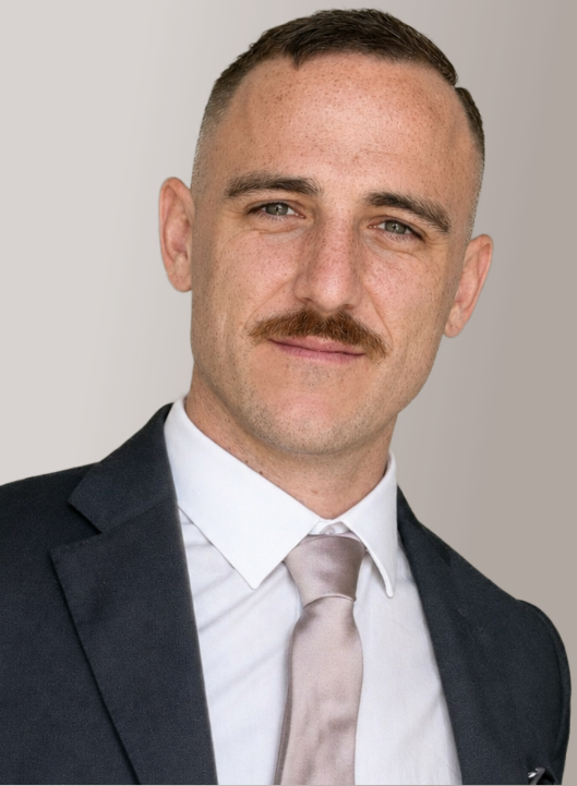
NAVAL ENGINEER · YACHT DESIGNER

The sea came first.
Engineering followed.

I turn curiosity for boats into design decisions, numerical models and buildable solutions—from first geometry to the shipyard floor.

Classic sailing yacht concept designed by Simone Mangieri underway at sea
ORIGIN / YACHT DESIGNCONCEPT TO ENGINEERING

CHAPTER 01 · THE VOYAGE

A passion shaped
into a profession.

The portfolio begins with the reason behind the work: a path through design, naval architecture, research and production engineering.

AGE 10

The nautical path

A fascination with boats became a direction long before it became a profession.

2014

Industrial design

Learning to turn an idea into proportion, geometry and a visual language.

2020

Nautical engineering

Adding hydrostatics, structures and performance to the design process.

2025

MSc research

Using numerical methods to investigate planing hulls and hydrofoil assistance.

NOW

Superyacht production

Connecting three-dimensional design with drawings, systems and buildability.

CHAPTER 02

Selected work

CASE / 001MSc RESEARCHSTATUS / VALIDATED NUMERICAL RUN

HYDROFOIL-ASSISTED STEPPED PLANING HULL

Can foil lift reduce resistance without losing equilibrium?

A custom MATLAB model coupled hull equilibrium, XFOIL data and a robust design search to answer one performance question.
−12.97%

predicted total resistance at the 6 m/s design condition

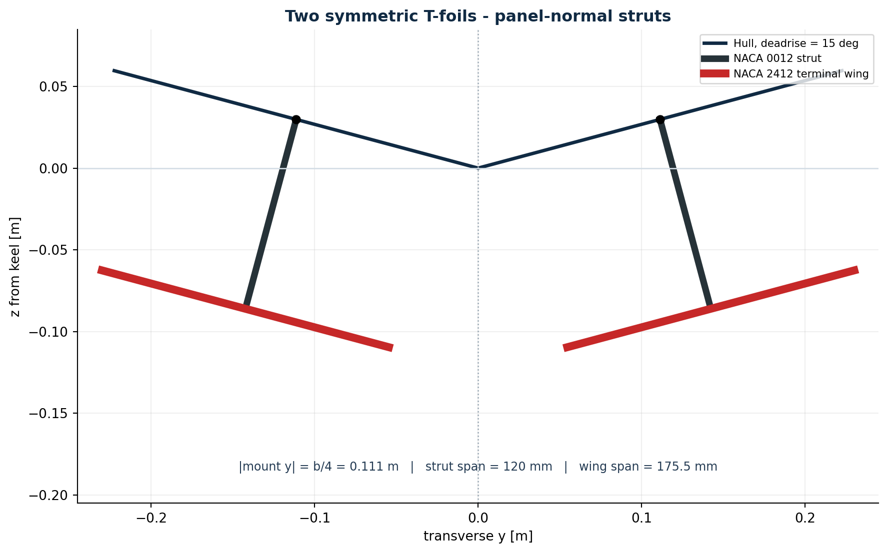
Transverse geometry of two symmetric T-foils beneath a deadrise hull
FIG. 01

Two symmetric T-foils with panel-normal struts.

NUMERICAL COREMATLAB
AIRFOIL POLARSXFOIL
HULL MODELSAVITSKY–BENG
DESIGN SEARCHROBUST OPTIMISATION
01 / MODELHull + foil equilibrium

Vertical force and pitch moment solved together.

02 / SEARCH648 configurations

Position, chord, spans and incidence explored.

03 / AUDIT10 neighbours

Local robustness and branch continuity verified.

View numerical workflow +

TECHNICAL DEPTH / METHOD

From geometry to one continuous solution branch.

Candidate equilibria were screened, checked around ten neighbouring states, recentred when needed and followed through speed without jumping between unrelated roots.
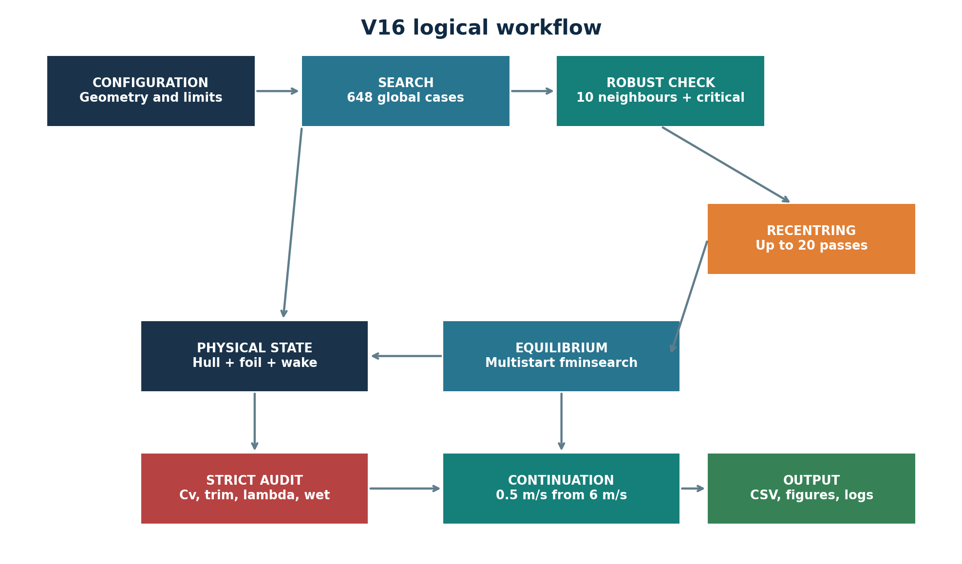
Logical workflow from configuration and search to audit and output
FIG. 02

V16 logical workflow—shown instead of source-code listings.

01 · PERFORMANCE

The curve tells the story.

Foil-assisted resistance stays nearly constant across the accepted speed range while bare-hull resistance continues to rise.
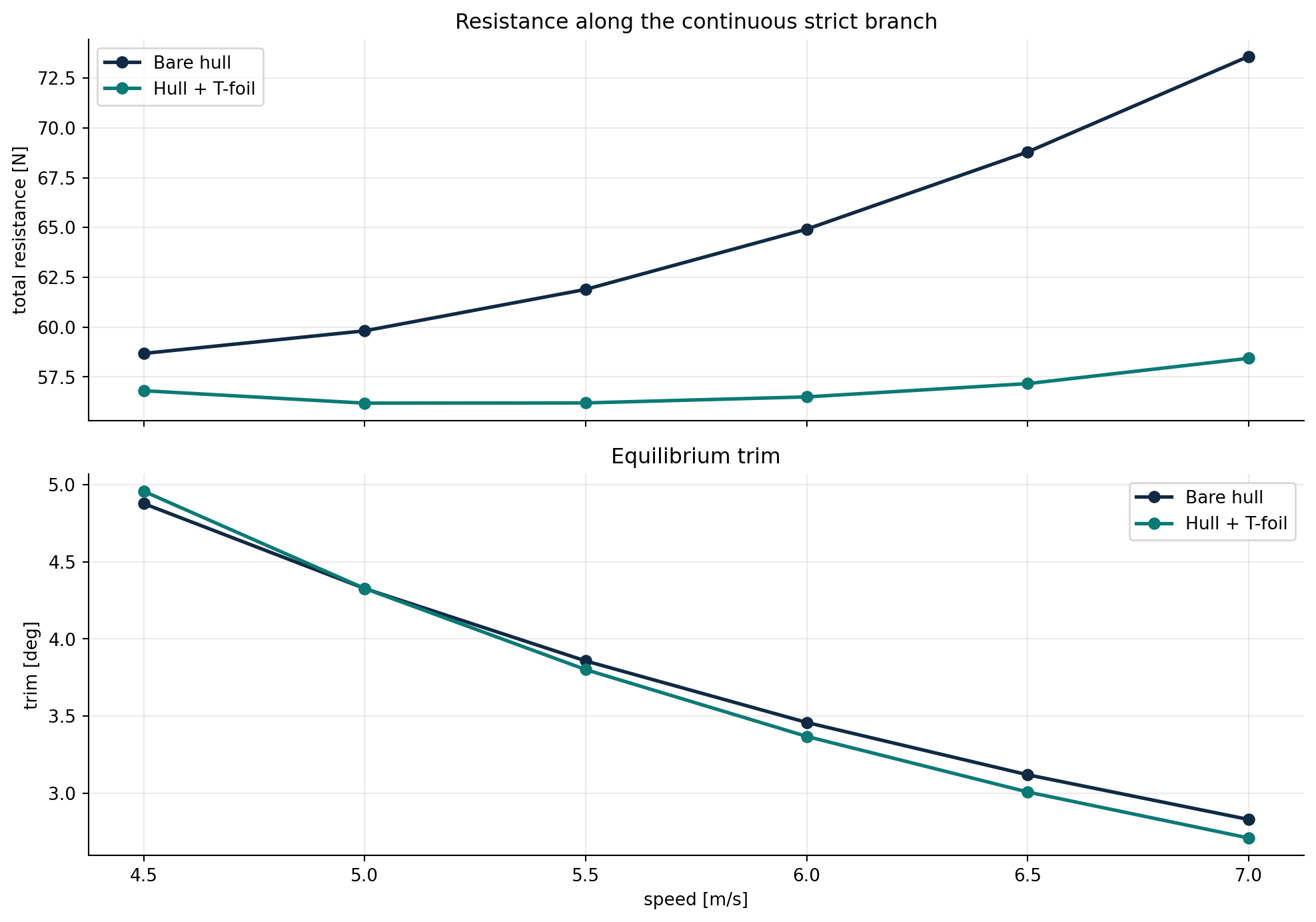
Resistance and equilibrium trim comparison across the strict speed branch
FIG. 03

Resistance and trim along the continuous strict branch.

RESISTANCE64.915 → 56.496N / bare hull to hull + foil
WETTED AREA−37.3%0.6529 → 0.4092 m²
FOIL LIFT SHARE32.15%of total weight
LOCAL CHECK10 / 10usable neighbour states

02 · ADJUSTABLE INCIDENCE

Fixed geometry.
Variable response.

The NACA 2412 terminal wing rotates about its quarter-chord pivot. Incidence decreases with speed to control lift while preserving the same equilibrium branch.
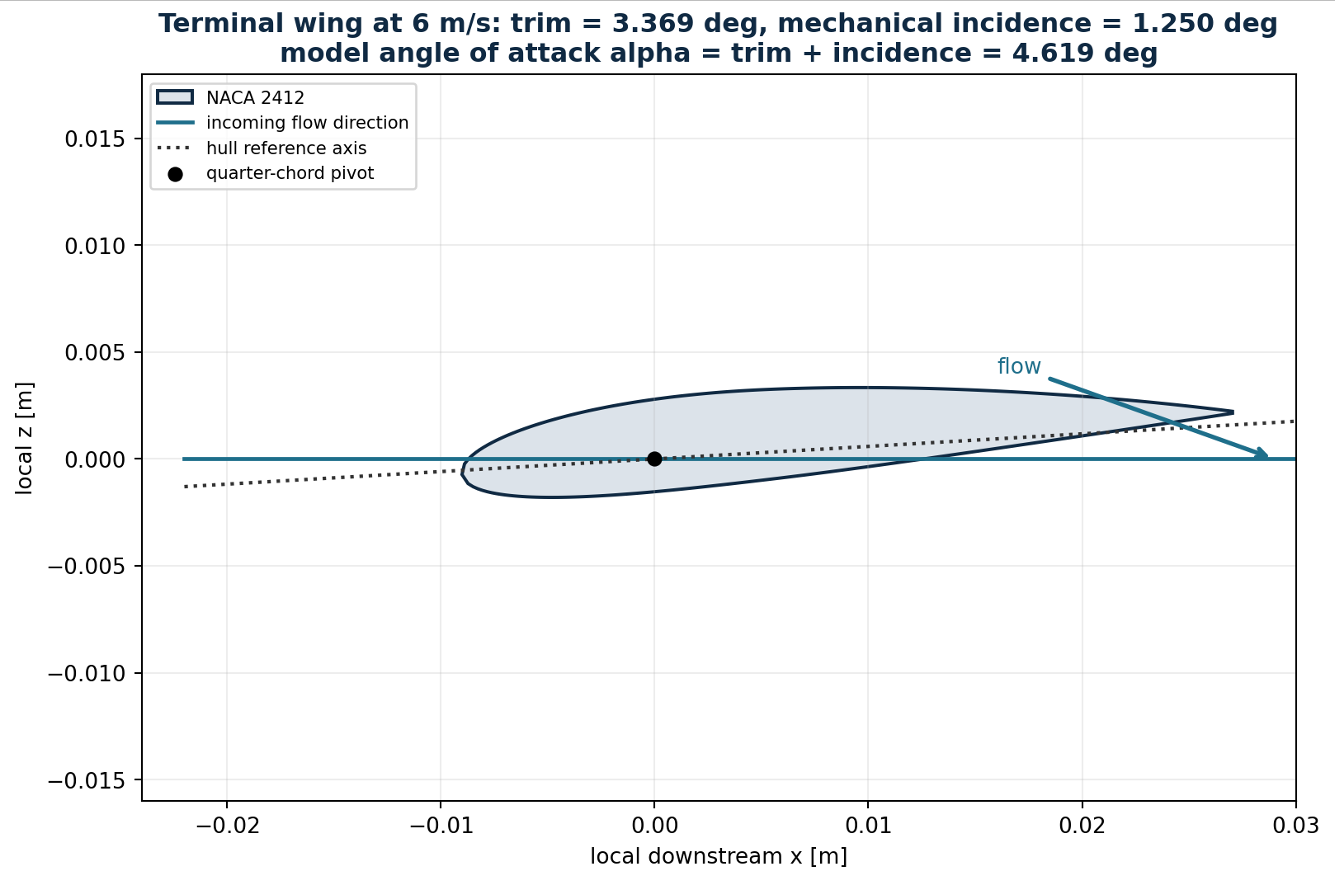
DESIGN POINT / 6.0 m/s3.369° + 1.250° = 4.619°trim + mechanical incidence = model angle of attack
NACA 2412 terminal wing rotating about its quarter-chord pivot at the 6 metre per second design condition
CONTROL DETAIL

Quarter-chord pivot and incidence reference at the design condition.

4.5—6.0 m/s+1.25°design incidence retained
6.5 m/s+1.00°first incidence reduction
7.0 m/s+0.75°upper strict speed
Mechanical implementation +

The numerical schedule defines the required motion. Actuator and hinge loads, positive locking, backlash, sealing, corrosion and a fail-safe position require mechanical validation.

03 · WHY IT WORKS

Less wetted hull, not free lift.

Foil lift and bow-up moment unload the hull. The resulting reduction in wetted area more than offsets the foil's own drag.
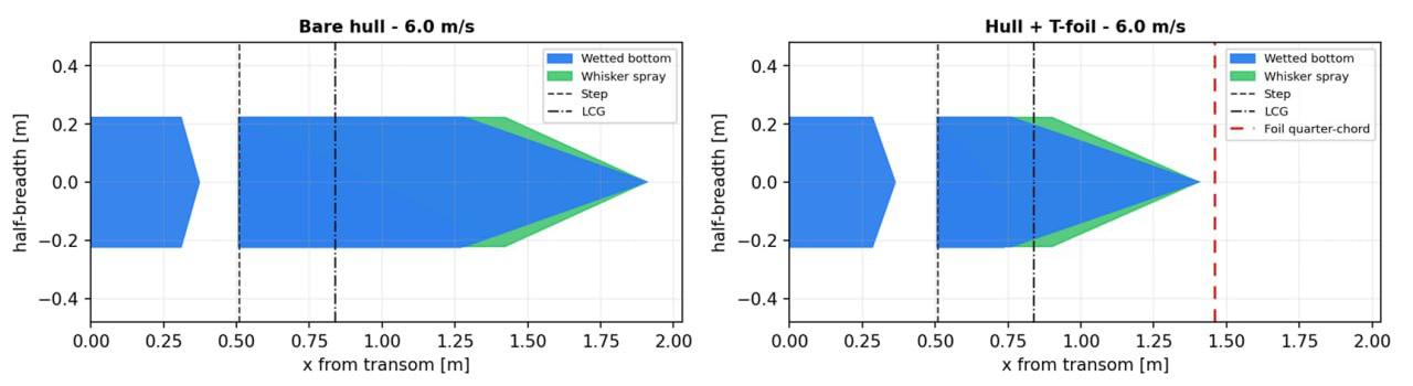
Bare-hull and foil-assisted wetted planforms at 6 metres per second
FIG. 04

Wetted planform comparison at the design condition.
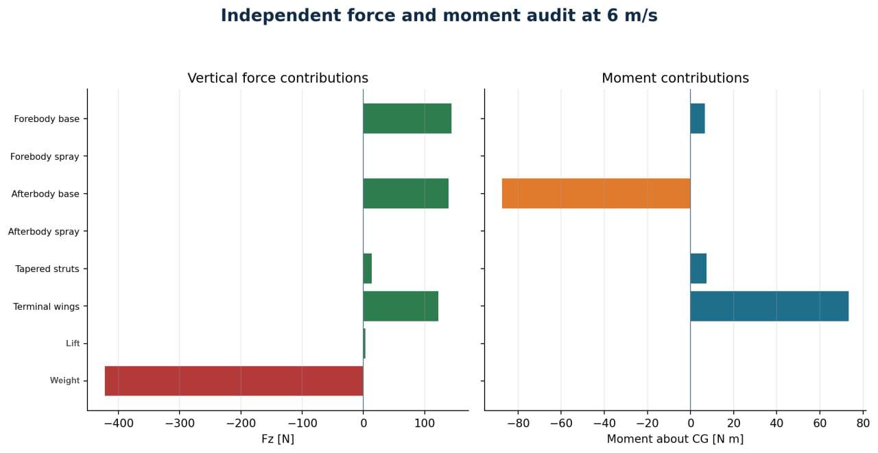
Technical validation & model limits+
Independent vertical force and pitching moment audit at 6 metres per second
FIG. 05

Independent audit of force and moment contributions.

WHAT THE RESULT MEANS

The selected state passes equilibrium, geometry and local robustness checks. It remains a preliminary quasi-static result—not CFD, structural verification or performance certification.

NEXT VALIDATION

Free-surface CFD, structural and ventilation assessment, followed by model or prototype testing.

THE TAKEAWAY

Model the physics. Challenge the result. Turn analysis into a design decision.
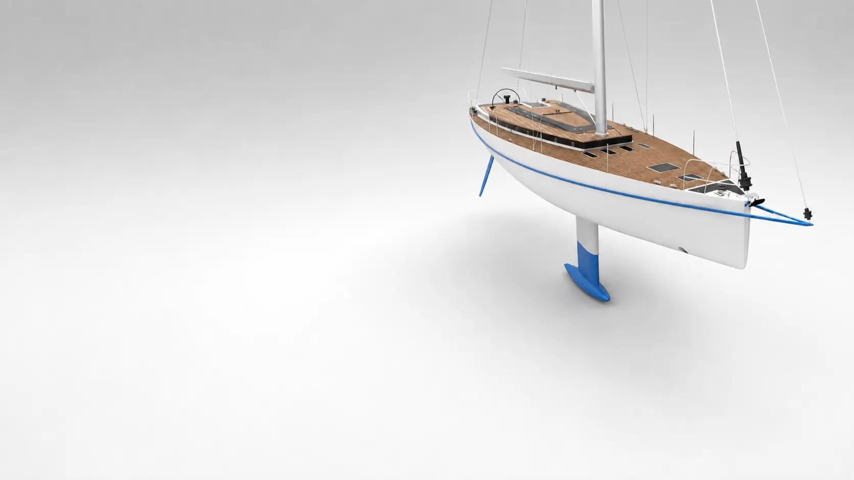
CASE / 002BSc THESIS2020 / INTEGRATED YACHT DESIGN
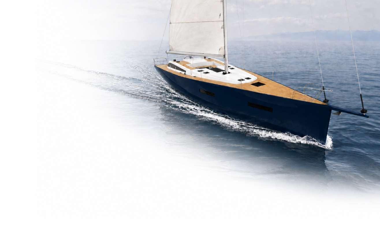
Three-quarter bow render of the 19.6 metre aluminium sailing yacht

19.6 M ALUMINIUM SAILING YACHT

Classic lines.
Contemporary engineering.

A sailing yacht conceived for ocean-going cruising and developed as one connected system—from general arrangement and aluminium structure to onboard systems, propulsion and stability.

3D MODELLINGRHINOCEROS
VISUALISATIONKEYSHOT
RULE-BASED CALCULATIONSEXCEL
STABILITY STUDYMAXSURF
LOA19.60 m
FULL-LOAD DISPLACEMENT21.20 t
HULL MATERIALEN 5083aluminium alloy
VARIABLE DRAFT3.00—4.15 mlifting keel raised / lowered

01 · THE DESIGN BRIEF

Not a retro yacht.
A modern yacht with a memory.

The brief preserved the character of a classic sailing yacht while rethinking performance, access, systems and life on board for a contemporary long-range cruiser.

CLASSIC DNA
  • Pronounced stern overhang
  • Central helm station
  • Traditional deckhouse proportions
  • Round side portholes
MODERN RESPONSE
  • Retractable lifting keel
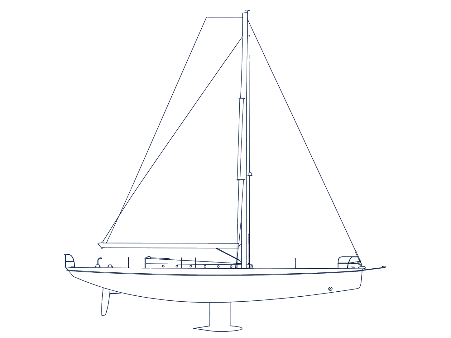
  • Square-top mainsail
  • Flush-deck integration
  • Accessible onboard systems

02 · FROM LINES TO LIFE ABOARD

Designing the whole vessel.

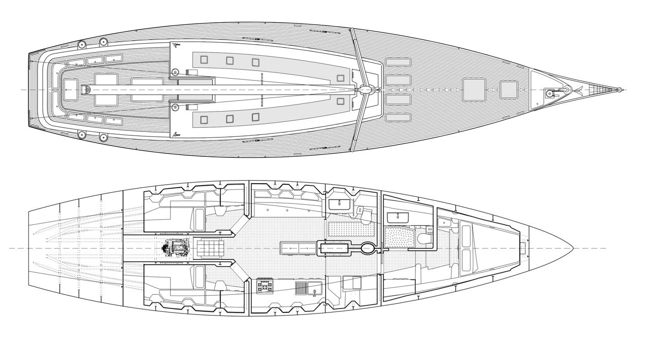
Exterior proportions, interior volume, structure and service access were refined together through an iterative design spiral.

Deck and interior plans of the 19.6 metre sailing yachtProfile and sail plan of the 19.6 metre sailing yacht

03 · STRUCTURAL LOGIC

Structure becomes architecture.

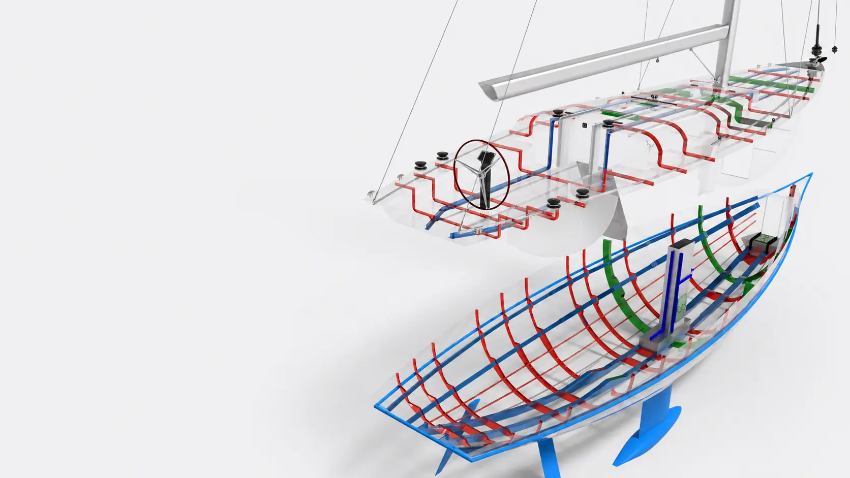
The EN 5083 aluminium shell, panels and stiffeners were sized in Excel from ISO 12215-5 rule formulas, then developed around the lifting-keel box, machinery, interior clearances and build sequence.

RULE-BASED SCANTLINGSWELDED CONSTRUCTION BLOCKSMAINTAINABLE ACCESS
Exploded transparent view of the sailing yacht aluminium structure

04 · ENGINEERING THE WHOLE

One yacht. One connected system.

The value of the thesis lies in coordinating each discipline—not presenting every calculation in isolation.

01ONBOARD SYSTEMS

Bilge, fuel, ventilation, fresh & sea water, waste, lifting keel, electrical system and steering layouts.

02PROPULSION

Resistance prediction, propeller selection and engine matching.

03STABILITY

Loading conditions, trim and righting-arm assessment.

TECHNICAL EVIDENCESystems, propulsion & stabilityEXPLORE+
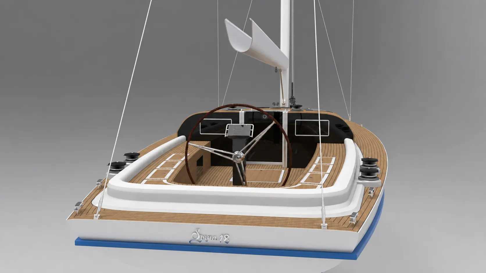
Cockpit and central helm render of the sailing yacht
THE TAKEAWAY

A complete yacht proposal, developed from silhouette to stability.

CASE / 003SELECTED ACADEMIC STUDIES · ANALOGUE STUDIOMETHOD / GRAPHITE ON PAPER

DESIGN FOUNDATIONS

Drawn to
understand.

Before CAD, drawing was the method used to investigate hull form, internal volume, construction and propulsion—one decision at a time.

FORMSPACESYSTEMS
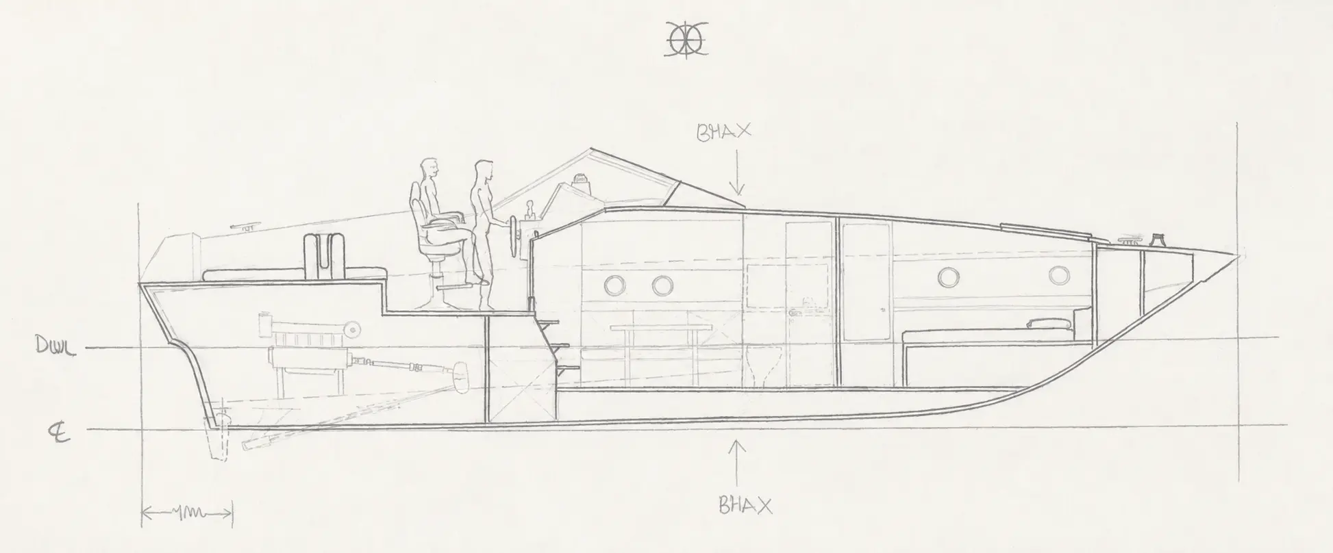
Hand-drawn longitudinal section studying the internal arrangement of a motorboat
01 / SPACE IN SECTION

Accommodation, circulation and machinery resolved through the longitudinal cut.

01 · SPACE IN SECTION

A section explains what a silhouette cannot.

The drawing connects exterior proportions with people, access, accommodation and the volume demanded by the propulsion system.

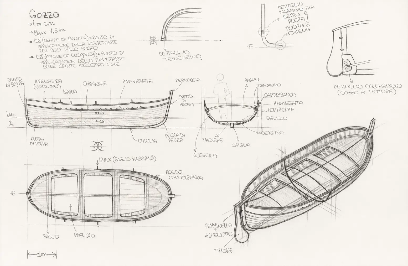
02 · CONSTRUCTION & TRADITION

Learning the boat through the way it is built.

A traditional gozzo study links hull geometry to frames, keel, planking and the vocabulary of small-craft construction.

Hand-drawn traditional gozzo study with profile, section, plan and construction perspective
02 / CONSTRUCTION & TRADITION

Hull form and structural anatomy considered as the same design problem.

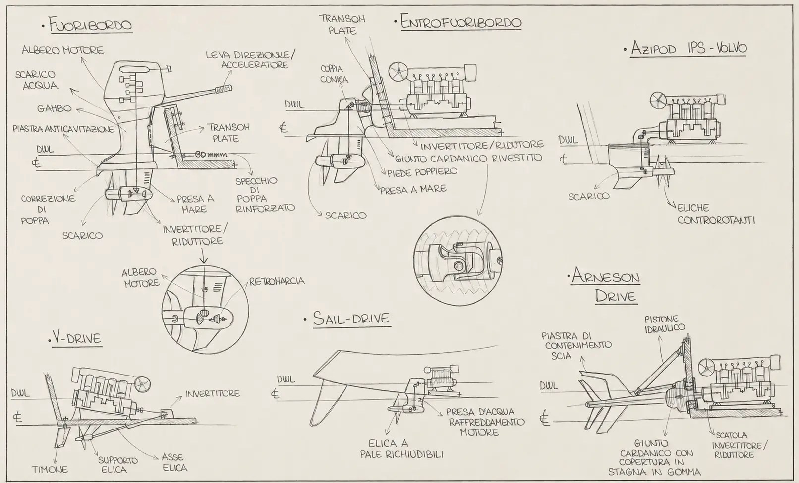
Hand-drawn comparison of outboard, inboard, IPS, V-drive, sail-drive and surface-drive systems
03 / SYSTEM COMPARISON

Alternative propulsion architectures studied through installation sketches.

03 · PROPULSION ARCHITECTURES

Every propulsion choice reshapes the boat around it.

Comparative sketches reveal how each propulsion architecture changes the relationship between machinery, structure and underwater geometry.

THE TAKEAWAY

Before CAD, drawing was the tool I used to understand the boat.

Portrait of Simone Mangieri
SIMONE MANGIERI

PROFILE / SIMONE MANGIERI

Design sensitivity.
Engineering discipline.
Shipyard awareness.

Naval engineer and yacht designer working at the intersection of concept, numerical analysis and production. Based in La Spezia, Italy.

Naval architecture3D modellingHydrodynamicsProduction engineeringTechnical communication
HAVE A PROJECT, ROLE OR IDEA?

Let's make it
work in reality.

mangierisimone@outlook.com